Home Brewed Projects and KitsThis page has information about home-brewed projects that club members have developed or kits they have purchased and built. The second meeting (4th Monday) of the month is available for project building, as well as other "show and tell" radio items of interest to members. Webmaster's note: I may not have all the recent projects on this page. If you would like me to add something, please send me an explanatory note about the project and, if possible, a picture or two. k2mun (at) arrl.net On this page: Hi-Pot Tester
Antenna Tuner
440 Amplifier
Regenerative Receivers
Seismometer
Code Practice Oscillator
Novice Transmitter
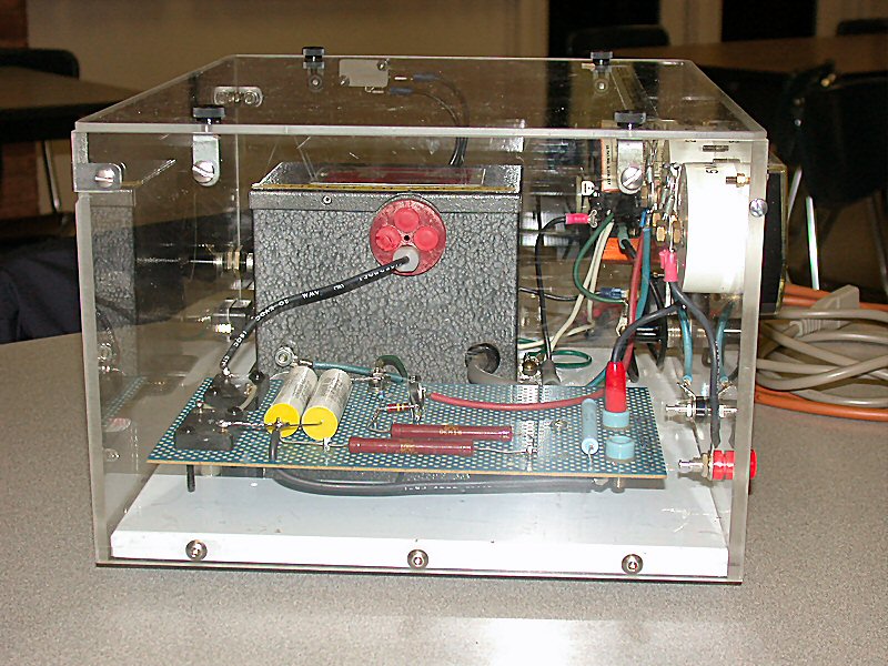
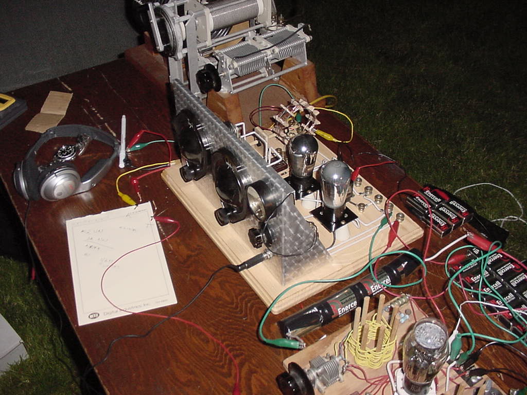
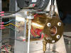
Rich Taylor N2AUG showed us this lo-cost, hi-pot(ential) component tester at a May 2006 meeting. The tester is used to subject a variety of electronic components -- diodes, capacitors, vacuum tubes -- to a variety of voltages (up to 10 kilovolts), but at low amperage (5 milliamps max). The tester will show whether the component is still capable of handling its rated voltage. The low amperage restriction prevents damage to the component. For example, current (amperage), as measured on the front panel amperage meter, should not flow in diodes and capacitors when voltage, as measured on the front panel voltage meter, is at or below the component's voltage rating. The large dial on the front of the tester is the voltage regulator.   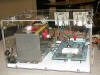
click on any image above to see a larger picture of the tester
Rich enclosed the tester components in a non-conducting, plastic case to prevent shocking the operator with potentially harmful -- even lethal! -- voltage levels. Rich has used the tester at hamfests to get a quick reading on whether or not a component is still working properly. Contact Rich for more information about the tester, including a schematic diagram and hints about acquiring the necessary parts.
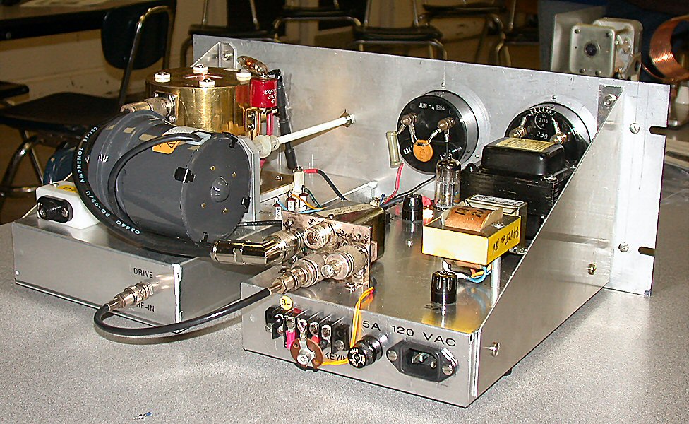
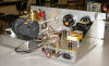
At the same May 2006 meeting, Rich N2AUG showed an antenna tuner (impedance matching network) which he made mostly from junk box parts and hamfest bargains. Why spend $100 for a commercial tuner when you can build one yourself for under $15? Again, contact Rich for more information about the tuner, including a schematic diagram and hints about acquiring the necessary parts. 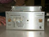 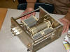
click on any image above to see a larger picture of the tuner
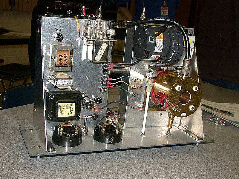
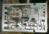
- Amplifier for 440 Band Transmitters by N2AUG
Rich N2AUG also built this vacuum tube amplifier for 440 band (70 cm) transmitters:
click on any image above to see a larger picture of the amplifier
- Regenerative Receiver Kits
A. In the Winter of 2006, many club members participated in a regenerative receiver kit building project. The $40 "Regenerative 4-Band SWL (Short Wave Listening) Receiver" kit was purchased from Ten-Tec. Members had a great time building their kits in a group setting at the fourth Monday meeting. Special thanks go to Rich Taylor N2AUG,who was the driving force in getting this project going and in providing technical assistance to the builders!
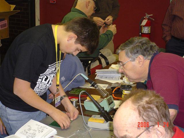
| Nick Esposito KC2ONP works on his regenerative receiver kit under the helpful guidance of Rich Taylor N2AUG
|
You can get more information about the 1054 Regenerative 4-Band SWL Receiver kit at the Ten-Tec web site
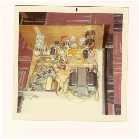
B. Here's a regenerative receiver built from scratch by James KB2FCV: Shown below are pictures of an 80 meter regenerative receiver I built back in 2003. A week or so before Dayton, I was perusing the ARRL website when I came across an article with building instructions and a schematic for a regenerative receiver.
http://www.arrl.org/news/features/2003/05/08/1/ The regenerative receiver is a 1920s two-tube radio design that uses 1920s 201As. I thought this would make an excellent companion to the single tube crystal controlled transmitter I built back in 1990 and recently used at the 2002 Field Day (using a K2 as the receiver). I started collecting components everywhere from Dayton 2003 to my junk boxes. Over the next month I started putting the receiver together. Andy WA2DKJ helped form the front panel (Thanks Andy!!). With less than 24 hours to go to Field Day 2003, the receiver fired up for its first time in Harry Kundrats Basement. Harry had the last remaining part I needed. Click on images for larger view: Since the club was running battery power for Field Day, both the transmitter and receiver were hooked up to many 9 volts and D cells! Eventually a car battery, inverter and power supply had to sub in for the transmitter as the D cells drained too fast but it was still battery powered! In the end I was able to make about a dozen QSOs using the pair. It was a bit of a challenge to get them tuned up but I was amazed that it worked and how well it performed. I must say its exciting and rewarding to hear and operate equipment that was put together with my own hands and be able to work stations. Its one of the main reasons I love to build. - James KB2FCV
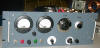
Above are photos of my first rig, a home-brewed novice transmitter. It was of "bread-board" construction. Back in 1969, as a novice (first WN2JVO and later WB2JVO when I upgraded to General a year later), we had to be crystal controlled with maximum 75 watts input. Quite frankly this rig with what looks like a single 6146 final amp was probably capable of more than 75 watts out!
It was built with a lot of assistance from my dad, W2IOC (SK) who must have found the circuit in an ARRL handbook or long defunct ham magazine. I do not have the schematic anymore, but wish I did. Maybe there is someone who may have some sort of clue? Needless to say, using this rig and working CW on the novice bands was the most enjoyment I have had in ham radio. It is a shame that this kind of experience is really no longer a part of being a new ham.
I found an interesting, albeit rather basic, website that recalls Novice days. Welcome to the Novice Historical Society:
http://www.novice.bappy.com/index.html
- Other past projects have included frequency generators (contact WA2DKJ) and sound card interfaces (contact KC2RLM).
|